Page index:
Page index:
Links back:


Surge Suppression
Modes of transmission
The following diagrams will explain the differences between the two main modes of transmission of an electrical surge via cables.
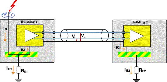
It describes a scenario whereby two buildings some distance apart both house electrical equipment shown as a yellow box containing an amplifier. Cables connect the pieces of electrical apparatus.
A conductor or high point on Building 1 receives a lightning strike which produces a current IB
to earth via the common earth bonding point and a ground stake.
Common Mode voltage
A Common-Mode surge produces a voltage between the ground potential and the functioning conductors. This is also called Longtitudinal Voltage and the potential difference VL is the same between each conductor and the earth (or screen) of the cable.

When the surge current IB arrives at the earth bonding point it tries to find its way to ground. Although most of the charge is dissipated via the ground stake, the earth resistance RE1 is high enough to allow some of the surge to enter the transmission line via the earth connection of the electrical apparatus.
The Common-Mode surge current IB2 travels to Building 2 where it finds its way to ground via the safety earth system.
The resultant temporary rise of the earth voltage in Building 2 applies a potential difference across the electrical equipment with respect to both the transmission line and the main power supply feed. This can cause serious damage.
Most buildings will not suffer such a direct hit by lightning. However the most usual damage occurs from a
![]() mains-borne surge created by a remote lightning strike.
mains-borne surge created by a remote lightning strike.
Normal Mode voltage
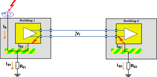
A Normal-Mode surge produces a voltage between the two functioning conductors. It is also called a Transverse Voltage and the potential difference VT induced by the surge is carried between the two functioning conductors.

It might be thought that the necessity for the surge current IB2 to have to jump to the transmission line in Building 1 and from the line to the equipment earth in Building 2 means that its power and effect are less than a Common-Mode surge (see above).
However the strength of an induced surge increases in direct proportion to the length of the edge of the inductive loops. The design of modern electronic equipment is such that there is little clearance between current conducting paths within the device, and not much more between the internal circuitry and the power supply earthed casing.
Not only does modern miniaturisation permit a greater induced current in adjacent circuitry, but the small distances between tracks on a circuit board also increase the risk of capacitative coupling.
In practice many of the Normal-Mode surges experienced by electrical equipment is actually produced within the same building by spark-overs from switches, back-emf from a motor stalling (eg in a lathe) and bulbs blowing in projectors etc. According the law of induction, surge voltages will occur in connected electrical cables anywhere that current changes very rapidly.
For this reason it is wise to power sensitive computer equipment from a separate ring-main, ensuring that there is no cross-bonding between its earth wire
and any other mains feed. The only way for a surge current to reach this 'clean' ring is to travel via the distribution board, where a
![]() surge suppressor can
be fitted to quench the over-voltage.
surge suppressor can
be fitted to quench the over-voltage.
Mains-borne surges
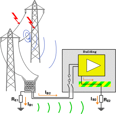
One of the most common causes of computer failure today is a mains-borne Common-Mode surge from a remote lightning strike or transient voltage caused by HT switching devices.

The voltage spike enters the building via the mains power cables, which raises the voltage across the electrical equipment by several thousand volts with respect to earth.
Although the same voltage is being grounded via the earthing rod at the local sub-station transformer, the ground wave IB1 (coloured green) reaches the building slower than the common mode spike transmitted along copper cables IB2 (propagation delay of electromagnetic radiation in copper = 2/3 speed of light).
The result is a "see-saw" effect with the computer equipment first receiving a high-voltage surge from the mains feed, and then the smaller ground wave a few seconds later.
This is not the only possible cause of surge currents. Overhead transmission lines close to a building will induce their own electromagnetic fields in the building and the cables within it.
Since all these surge currents need to find their way to ground, they can effectively be nullified by a suitable anti-surge device connected across the phase (live) and neutral at the mains distribution board in the building.
Such an anti-surge device must be adequately rated to handle surge currents of the magnitude induced by lightning strikes.
We recommend the use of ![]() ValveTrab units for which the specification is given
ValveTrab units for which the specification is given
![]() here.
here.

Low-level anti-surge devices housed in mains power plugs are simply inadequate to handle the energy involved and are placed too far away from the earth bonding point to permit
sufficient current to be dumped. Indeed it is likely that most modern computer equipment already has a higher level of transient rejection built into its power supply.
Contact details for ExpLAN Computers Ltd can be found on the ![]() ExpLAN homepage.
ExpLAN homepage.